Converting a Modular Hand Well Pump to a Motorized Well Pump (Legacy LBLD)
Note for existing LBLD motor owners: The LBLD Motorized Well Pump and LBLD Solar Kit were discontinued for new purchase on March 31, 2026. Parts and service stay available for at least 10 years. This article is still here as a reference if you own one of those systems.
If you're looking for a new automated pumping setup with manual backup, we built something better. Check out the Inline Manual-Solar Well Pump System (WORKHORSE solar submersible plus Simple Pump hand pump, no switching between them). For support on your existing LBLD system, see /support/lbld-legacy.
A hand well pump has probably given you a ton of value over the years. But things change, and what worked for you a few years ago might not fit your needs today.
Simple Pump's modular design lets existing hand pump owners add the LBLD motor without replacing the whole system. The drop pipes stay. The cylinder stays. The pump head stays. You're adding a motor unit on top. For LBLD owners who installed this kit, it saved them thousands compared to putting in a full motorized system from scratch.
A note for new customers: This guide covers the LBLD conversion, which is no longer available for new purchase. If you're planning a new installation and want both automated pumping and manual backup, the current product is the Inline Manual-Solar Well Pump System. It pairs a WORKHORSE solar submersible with the Simple Pump hand pump and lets both run at the same time, with no swap between modes.
Replacing your hand pump with a fully automated system from scratch can be expensive. If you already have an LBLD kit and you're doing the install yourself, the steps below walk through the process.
Pre-Planning
The Ideal Pumping Configuration
First you need to know the temperature of where you will be placing your pump.
DC motors operating in ambient temperatures above 100˚F lose operating efficiency. This means if the site you are looking to install your pump into regularly peaks past 100˚F, it’s recommended trying to place it in a shaded area.
This also applies to the component box, which needs to be mounted near the batteries in an ideal environment that is out of the sun because of the electrical components contained inside.
Next, you need to figure out the total dynamic head (TDH). This head limit will provide water within a specified limit and is based on the pumping cylinder that you have bought. Three factors come into play when calculating the TDH, but not all of them will always be applicable to every install:
- The lift from the static water level.
- Any vertical distance from the well head.
- Any pressure that is being pumped
As you calculate your TDH, ensure you take into account which of the three factors will be needed during your install.
An example of this is:
Static Water Level: 78’
Additional Vertical Lift: 16’
Pressure: 100’ (45 PSI)
TDH: 194’
Make sure the calculated TDH fits the limits of your pump, and if things don’t add up, don’t worry, there are always alternative methods to make sure the goals of your pump are met.
Other evaluations to be aware of before you start include:
- Can keep your voltage above 11.5 or 23.5 volts?
- Will you need a transfer pump to reduce your TDH?
- Have you decided to wire in a pressure switch to control the “On” and “Off” state of your pump system?
If you are having trouble figuring any of these questions out, we recommend reaching out to someone who is certified by the North American Board of Energy Practitioners (NABCEP) and has experience configuring off-grid systems.
Starting the Install
Ensure all of the items are in the box and make sure you have the following tools:
- (4) Allen wrenches: 9/64”, 3/16”, 5/16”
- (2) Channel lock pliers
- (1) Medium Phillips screwdriver
Power Source
Now it’s time to figure out your power source. We recommend using deep-cycle batteries, as the Simple Pump motor system isn’t designed to run directly from a panel. You can also use AC power, but please make sure you have the correct AC-to-DC converter that is rated to handle your model’s power.
Finding the right location and storage for the power source that is not only safe but avoids an increased voltage drop is key.
Following the tips we gave in the earlier section, try and place the power source and control box as close to the well head as possible. With the two sets of cables from the box, you need to connect the batteries to the control box using the 4’ cables and the control box to the motorized system using the 12’ cables.
No matter the power source you decide on, both the both the power and the control boxes need to be protected from the weather elements. And while the control box is slightly weather resistant, it’s not weather proof.
The last thing before we get to your existing pump is preparing the linear bearing link drive (LBLD) control box. Use your 9/64” Allen wrench and remove the six screws that attach the linkage cover. Just set these to the side in a safe place for later and finish off by cutting the zip tie that secures the clevis.
Converting Your Existing Hand Pump
Ensure that the hand pump that you already have installed works fine before installing this gear motor.
The best way to do this is by confirming that your pump is delivering at least one gallon of water with approximately 25 strokes if you have the Simple Pump model 100. For the model 125, the pump should be providing the same gallon in approximately 15 strokes.
Now it’s time to start converting.
Using the 3/16" Allen wrench, remove each of the four fasteners holding the lever arm mechanism to the pump head. Then remove the lever arm bracket and lever when they are still connected to the 3/4" stainless rod. As a reminder, the threads are reversed, meaning the direction to remove is clockwise instead of counterclockwise.
Before you start adding the 13” rod extension to the pump, please verify the height of your existing pump rod. To get a the proper measurement, follow these steps:
- With the pump rod at the bottom position, measure from the rod gland to the base of the threads on the pump rod.
- Your pump rod will need to sit somewhere between level with the rod gland and less than 3.0” above it.
During your measurement, if you notice it is above 3.0”, your hand pump will need to be adjusted before you continue. Take a peek at your original hand pump instructions for the details on how to bring your lift rod protrusion down.
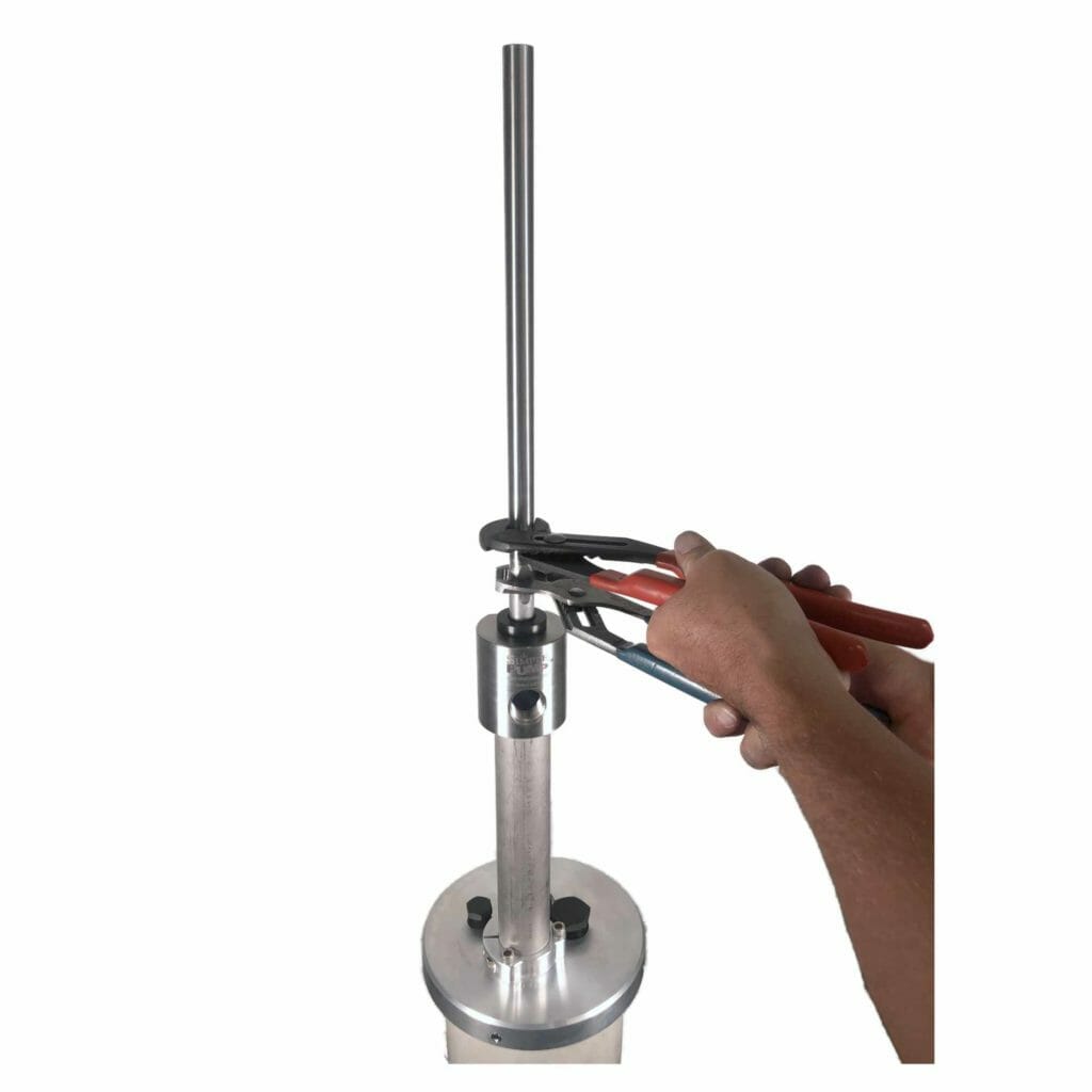
Now add the 13” rod extension to the top of the existing pump rod, keeping in mind the reverse threads mentioned above, and finish by using the two channel locks to tighten.
As a small note on this section, half of your riser tube must be below the well cap.
Install Your Converted Pump
Because the weight of the pump can be around 30 pounds, it’s recommended you get someone to help you finish the install.
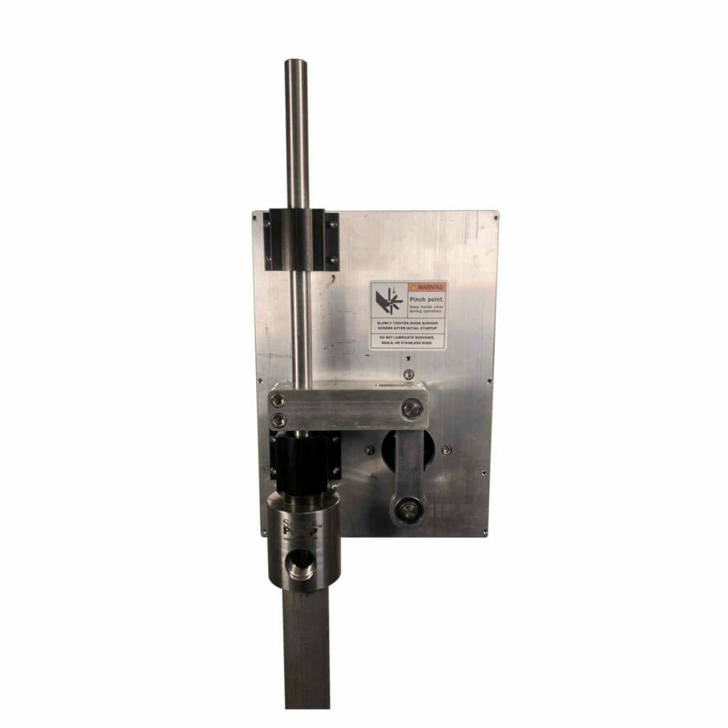
Ensure you have oriented your unit correctly before moving forward. The cabinet portion faces away from the pump head, and the bottom is where the two MC4-style plugs will be.
Make sure your clevis is in the bottom position, and start lowering the assembled unit onto the pump head. As you lower, the rods should move through the following pieces in this order:
- The lower linear bearing
- The clevis
- The top linear bearing
A bit of wiggling of the yoke while lowering might be necessary to get your unit to drop all the way.
There should be about 1/4" of space between the bearing housing and the top of the rod gland when the holes are fully aligned. The rod gland should also be your most exposed piece on the pump head.
Finish by screwing the four 1/4-20x3/4” SS SHCS mounting bolts through the holes just aligned and fastening the mounting plate to the pump head.
Piston Positioning
One of the most important steps of the installation is ensuring that the piston is in the correct spot.
Start by pulling up on the 13” rod extension with the knowledge that depending on your static water level, it could take a decent amount of work to lift the rod.
Then, using a 5/16” Allen wrench, tighten the two stainless steel socket head cap screws on the clevis, which should pinch the clevis to the rod. Make sure both of the screws are very tight.
The Right Alignment
Now you need to check your pump rod alignment with the linear bearings and mounting plate.
Ensure all eight 8-32x1/2 SS socket head cap screws holding the top and bottom linear bearings are loose and remove the four holding the top bearing.
Because this step is only done for the top screws, you then need to compare the placement of the holes in the linear bearing with the holes threaded into the mounting plate.
If the holes don’t line up, consult the full installation manual for adjustment instructions.
Once the alignment is good, tighten all of the screws holding the assembly to the pump head. You can also put back the four 8-32x1/2 SS cap screws into the top linear bearing.
The Electrical Connections
Make sure the on/off switch is in the “Off” position during all electrical work.
Using the cables we spoke about in the beginning, we are now going to start connecting your battery and the control box (remember because the cables are only 3” long, the control box needs to be installed close to the battery).
Connect the red cable to your positive terminal on the battery and the black to the negative. Follow this up by using the two 12” cables to create a connection between the control box and the LBLD unit. Make sure the red cable connects to the two positive leads and the black cable to connect the two negative leads.
Your pump should now be fully powered and ready to turn on.
The Finishing Touches
The initial startup for your pump is done without the cover installed, so the pinch points will be exposed. Please use extreme caution.
During the first startup and break-in period, leave the pump outlet open or pump through a short drinking-water-quality garden hose. The break-in period should take around six hours, and make sure the power source you chose can provide power for the full six hours.
Once you switch the unit on, let it run until you start getting water. Once you start to see water be produced, begin to tighten the screws on the linear bearings, but beware of pinch points while tightening.
Start with the top two screws in the upper bearing first, followed by the lower two screws on the bottom bearing. This is to help avoid those pinch points.
Let everything run for about five minutes, then turn the system off. Do a final check for the temperature of the pump rod sticking out above your unit. If it is really hot, you may have a binding issue, and you should re-verify your alignment that we spoke about earlier.
Tighten the remaining loose screws and, using your 9/64” Allen wrench for the six 8-32 SS SHCS, attach the cover to the mechanism’s mounting plate.
Start your system up once again for the six-hour break-in, and you now have finished converting your hand pump system into a fully motorized well pump.
If you need additional details, be sure to check out our manual that has more details on the information here.
We hope you have just saved a ton of money and time converting your hand well pump with the Simple Pump conversion kit.
Be sure to reach out to us if you have any additional questions.
Ready to Get Started?
Installing a Simple Pump system is easier than you think. Request a free quote to get a custom system recommendation for your well, or contact our experts for personalized guidance.
Questions about installation? Call us at (877) 492-8711 or find a certified dealer near you for professional installation support.
Tags:
Ready to Get Started?
Get expert help choosing the right well pump system for your specific needs. Our team has 25+ years of experience in reliable water systems.